
AUTOREDLINE BLOG / DRAWING COMPARISON
Pixel diff vs engineering redline: what is the difference?
A pixel diff shows where a page looks different. An engineering redline shows what changed in the drawing requirements. Moving an unchanged view makes that distinction clear.
1. The view moved. The part did not change.
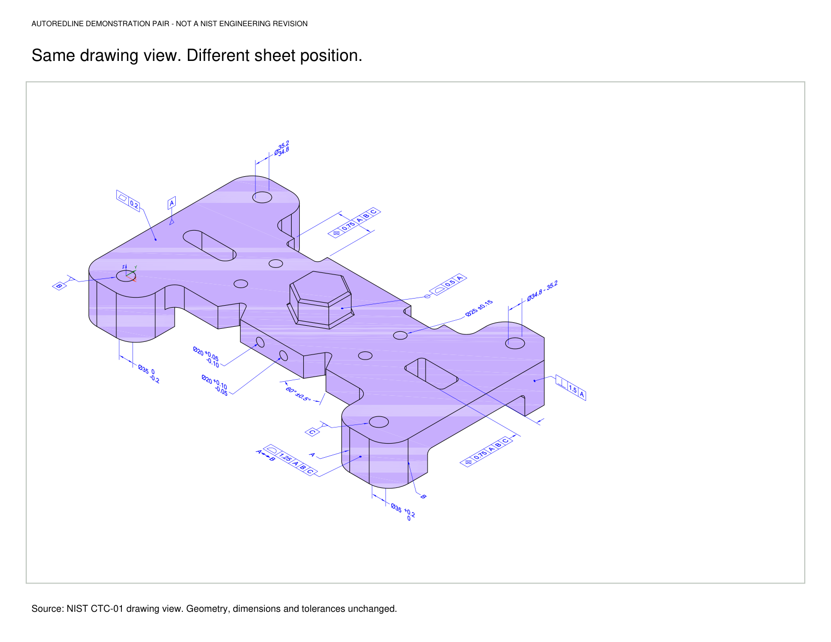
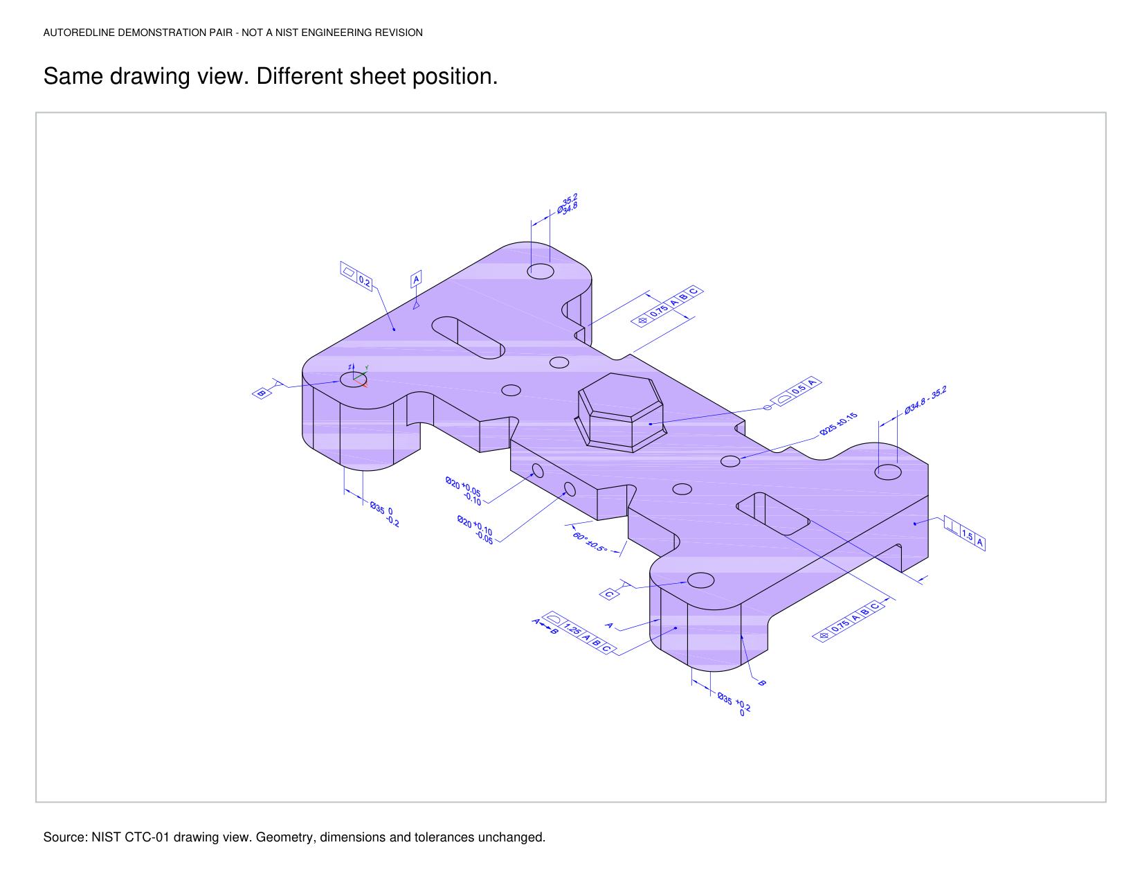
The same drawing view and all its callouts move to the right on the sheet. No hole, surface, dimension, or tolerance changes. A simple pixel diff flags both the old and new positions. Treating those flags as removed and added part geometry would produce an incorrect redline.
The reviewed engineering redline keeps the original view intact: there is no engineering requirement to strike out or replace. A sheet-layout change can be recorded separately if your revision process requires it.
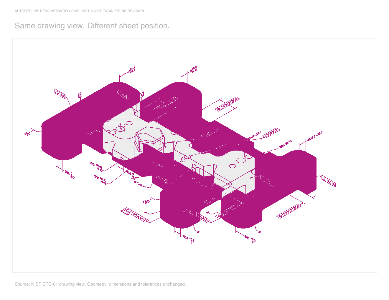
Flags both positions, although the part is unchanged.
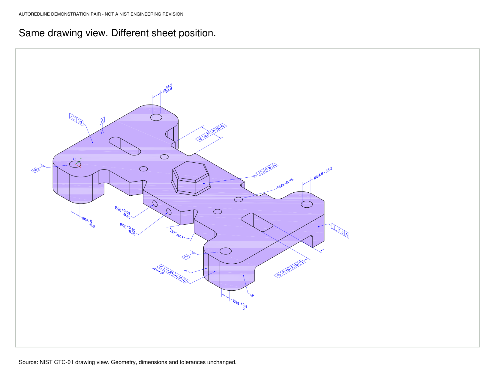
No geometry deletion or addition. The requirements are unchanged.
See the original and revised views
2. One changed digit. Four affected holes.
Here the shared 4X Ø.625 ±.005 callout becomes ±.002. The nominal hole size and geometry stay the same. The pixel diff locates the changed digit; the redline communicates the replacement tolerance and its scope: all four switch mounting holes. Crossing out the holes would misrepresent the change.
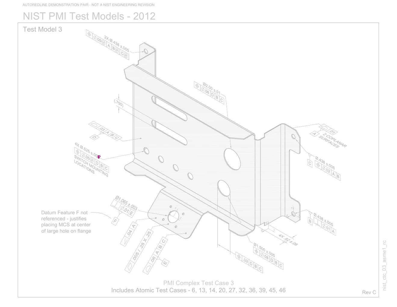
Highlights the changed tolerance digit.
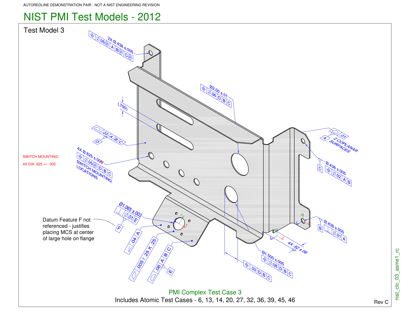
Shows the replacement requirement for all four holes.
See the original and revised views
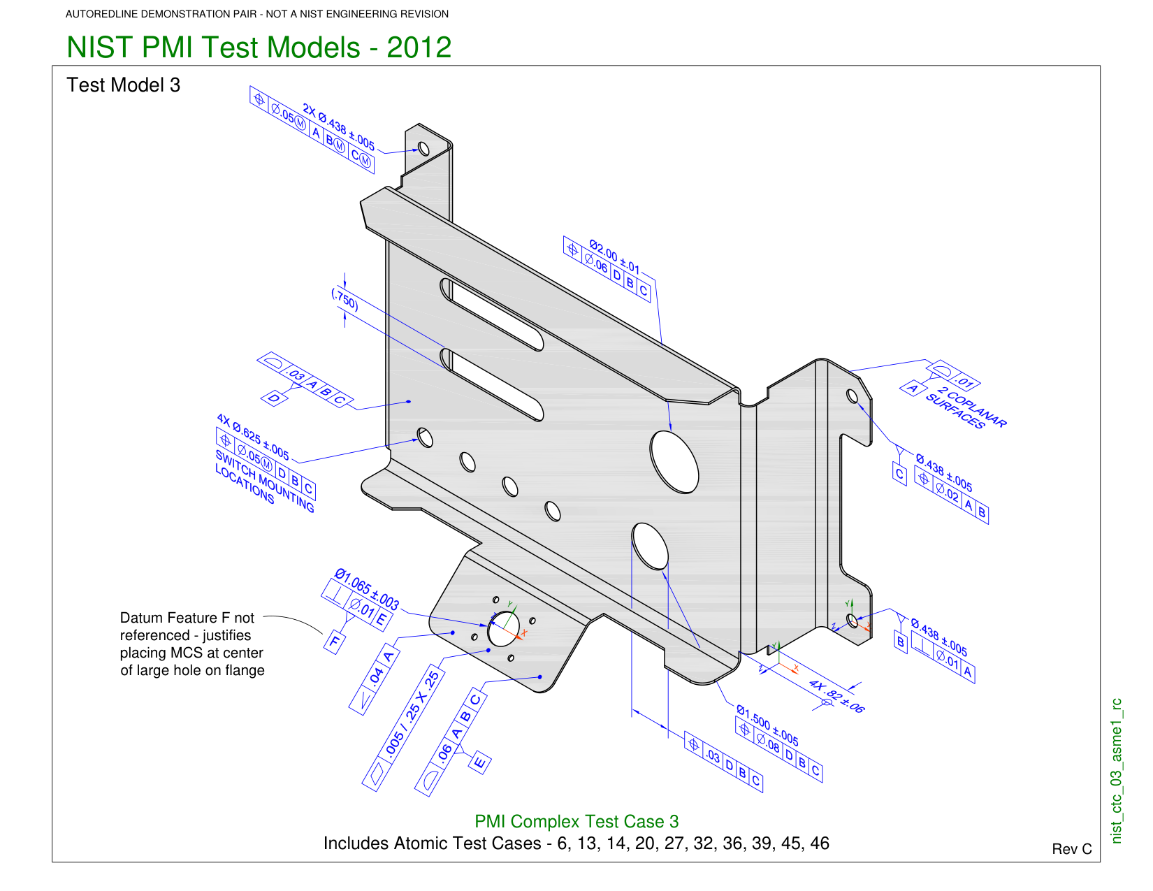
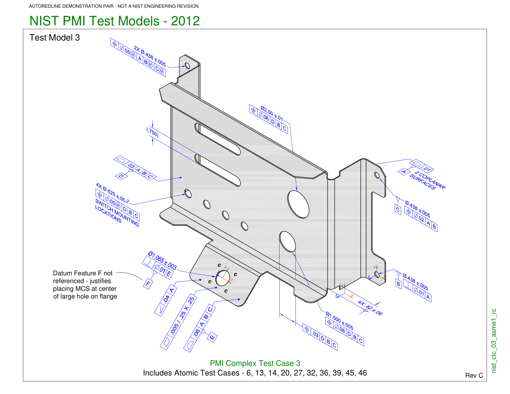
3. A small visual change can have a wider scope.
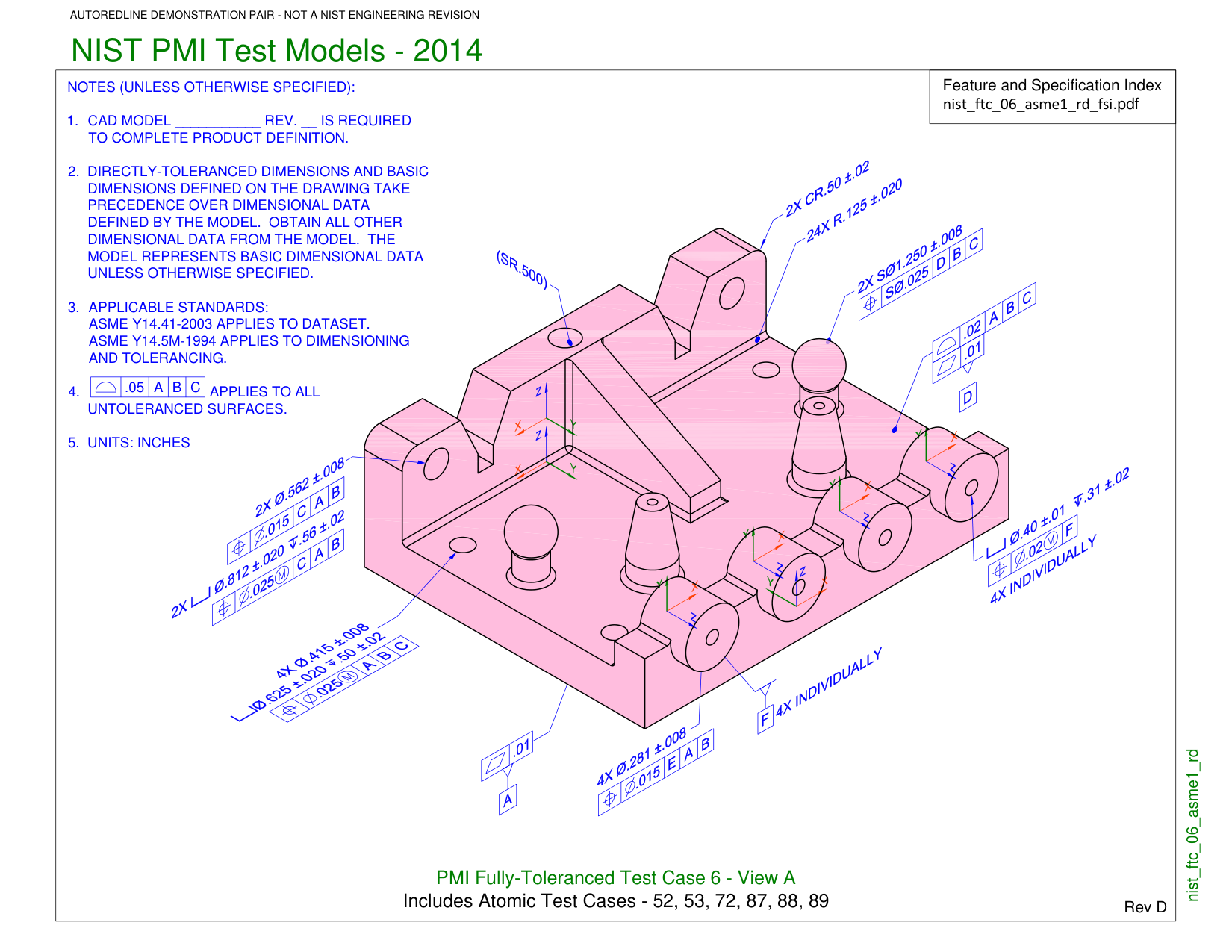
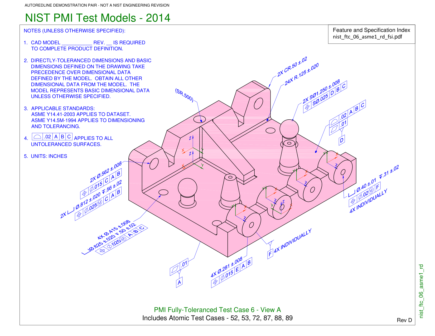
In note 4, the general surface-profile tolerance changes from .05 to .02 inches, with datums A, B, and C unchanged. Only a few pixels differ, but the requirement applies to the untoleranced surfaces covered by the note. The redline shows the new requirement in context.
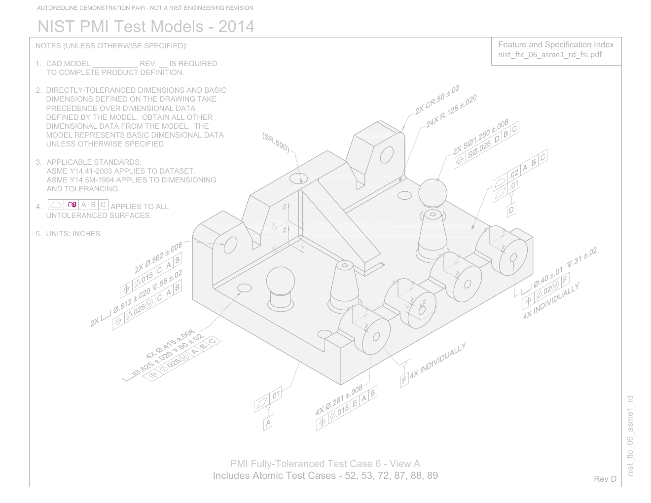
A small highlight shows where the digit changed.
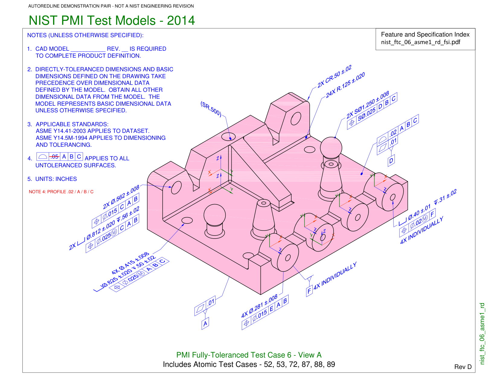
Strikes the old value and identifies note 4 and its datums.
See the original and revised views
What AutoRedline adds
Pixel comparison, colored overlays, and text diffs help find differences. A useful engineering redline turns those differences into drawing markup: the affected feature, the old requirement, and the proposed replacement or addition.
AutoRedline prepares editable proposals from your original and revised drawing PDFs. Review the marks, correct omissions or misinterpretations, and export the reviewed PDF. The reviewer decides whether the change is correct and ready for approval.
Alignment and content matching can reduce false flags in comparison tools. The pixel maps above use a basic unaligned comparison to show why a visual difference still needs engineering interpretation.
Two common questions
Should a moved object always be ignored?
No. Repositioning an unchanged view on the sheet differs from moving a hole or feature relative to the part. A changed feature location is a real engineering change and needs a redline. Compare the geometry and requirements, not just page coordinates.
Is a pixel diff the same as a redline?
No. A pixel diff identifies visual differences. An engineering redline communicates a drawing revision. A diff can help prepare or check a redline, but each highlighted region needs interpretation.
Examples use public NIST CAD/PMI test drawings with demonstration edits and reviewed markup, not untouched AI output or NIST revision history. NIST does not endorse AutoRedline. Source collection.