
ENGINEERING DRAWING GUIDE
What is an engineering redline, and why does it matter?
An ECO review becomes difficult when the reviewer can see that something changed but cannot tell which revision the markup started from, what the old requirement was, or how the new requirement should appear on the drawing. A useful redline puts that evidence in one view.
Developed with practical review input from an engineer who works with controlled drawing revisions and ECOs.
A drawing change is rarely just one sentence
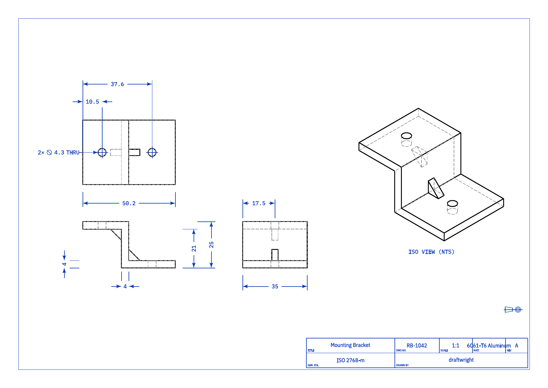
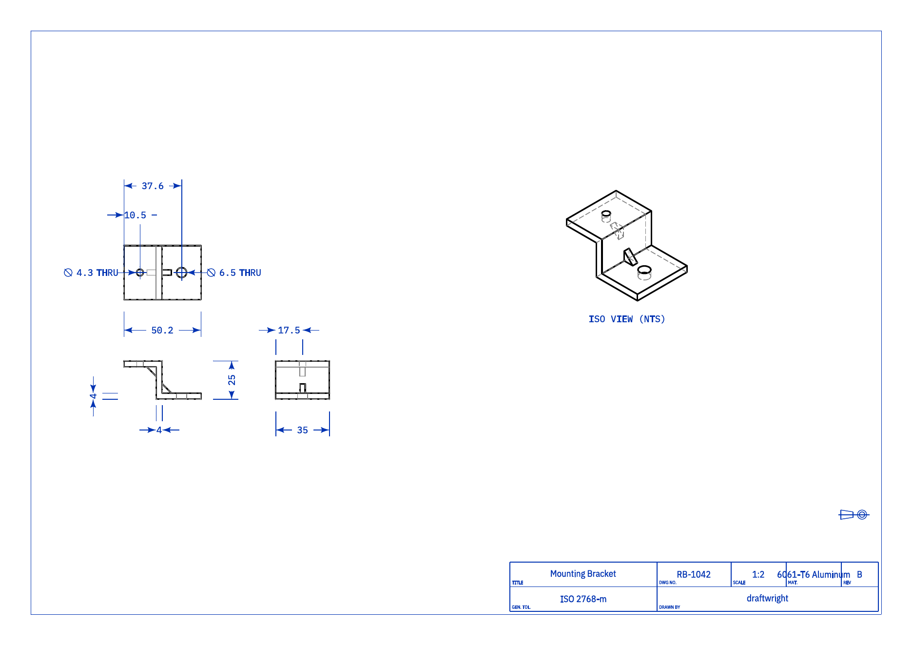
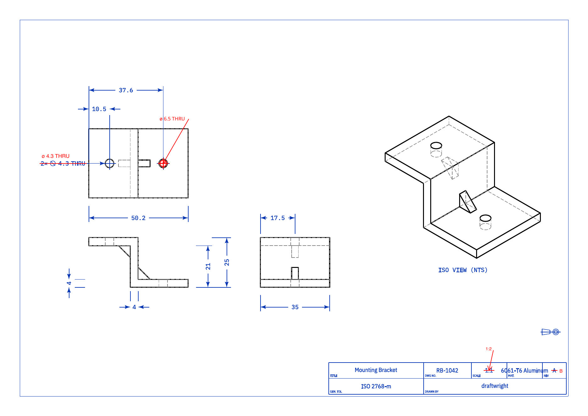
A practical concern raised during review is that a marker can show where to look without showing what the reviewer needs to compare. Consider a simple instruction: “Increase the hole diameter to Ø6.5.” Which hole is changing? What was its previous diameter? Was the instruction written against Revision B, Revision C, or an unreleased working copy? Does a shared quantity callout need to be split? Does the inspection plan still refer to the old value?
When the original drawing, revised drawing, email, and change request all live in different places, each person has to reconstruct the change. Two careful reviewers can reach different conclusions because they are not looking at the same representation of the proposal.
A redline reduces that reconstruction work. It brings the relevant part of the old drawing and the proposed change into the same review artifact before the controlled revision is prepared and released.
What an engineering redline actually does
An engineering redline is a marked-up drawing that communicates a proposed or required change at the point where the change occurs. Depending on the organization’s convention, it may strike through an old value, add a new value, point to affected geometry, or include a short note explaining what must be revised.
Red is only the convention. For review purposes, the document must answer three questions without forcing the next person to repeat the comparison:
- Where is the change? The mark is attached to the affected feature, callout, note, or table entry.
- What was there before? The previous requirement remains identifiable where the team’s convention requires it.
- What is being proposed now? The new value or instruction is clear enough to review and implement.
Why not communicate the change in an email or with CAD markup?
Sometimes that is enough. A team working in the same CAD or PDM system may be able to preserve the model, its revision history, and every linked change record. The difficulty begins when a markup is exported, copied into an ECO, or sent to someone who does not have the same files and system access.
A CAD markup may place a numbered balloon or revision marker beside a feature, then explain the change in words somewhere else. It can show the reviewer where to look without showing what was there before. Once that file is separated from its native history, it may also be unclear whether the marker was created against Revision B, Revision C, or an unreleased working copy.
A redline is not a failure-investigation record. Its first value is during the ECO review, when Engineering and Quality need to understand the exact proposal and respond to the same baseline. Later, if the team needs to determine which requirement applied when a part was built, a clear redline can help explain the change, but the released drawings, approvals, and controlled revision history remain the records that establish what was official.
These methods are not mutually exclusive. CAD comparison can find differences, the change record can document the reason, and the redline can give the wider review team a clear before-and-after artifact. The released drawing and controlled revision history remain the official record.
Where redlines are most useful
Redlines earn their place when several people must review a drawing change before the next revision becomes official.
Prototype and test feedback
A prototype build may reveal that a tool cannot reach a fastener or that a cable rubs against an enclosure edge. Marking the proposed feature, its old position, and its new position on the drawing gives Mechanical, Manufacturing, and Test one proposal to review before anyone edits the released CAD definition.
Manufacturability and supplier feedback
A supplier may ask for a larger internal radius or a tolerance that matches a capable process. A written request captures the intent, but the redline shows which feature and callout are affected, what value is being replaced, and whether the same requirement appears in another view.
Transfer from development to production
During transfer, an assembly method that worked for a few prototypes must become a repeatable production requirement. A redline lets the team review the exact dimensions, notes, materials, and inspection characteristics that must change before work instructions, fixtures, and inspection plans are updated.
Corrections to released drawings
A released drawing may contain an outdated note, an inconsistent view, or a missing callout. The redline makes the correction visible without presenting the proposal as an already approved revision.
Regulated product development
In a regulated product, a small mechanical change can affect risk controls, verification, manufacturing instructions, inspection methods, labeling, or service documentation. The FDA’s current Quality Management System Regulation incorporates ISO 13485:2016 as the quality-management framework for medical-device manufacturers. It does not require a particular redline format. A redline can support the review by making the proposed drawing change explicit, while the organization’s approved quality-system records remain the controlled evidence.
Two complex examples where one mark is not the whole change
On a production drawing, geometry, tolerances, datums, notes, fasteners, and inspection requirements form one connected definition. The difficult examples are not the ones with the most red marks. They are the ones where a small visible change alters how the part is made, inspected, assembled, or serviced.
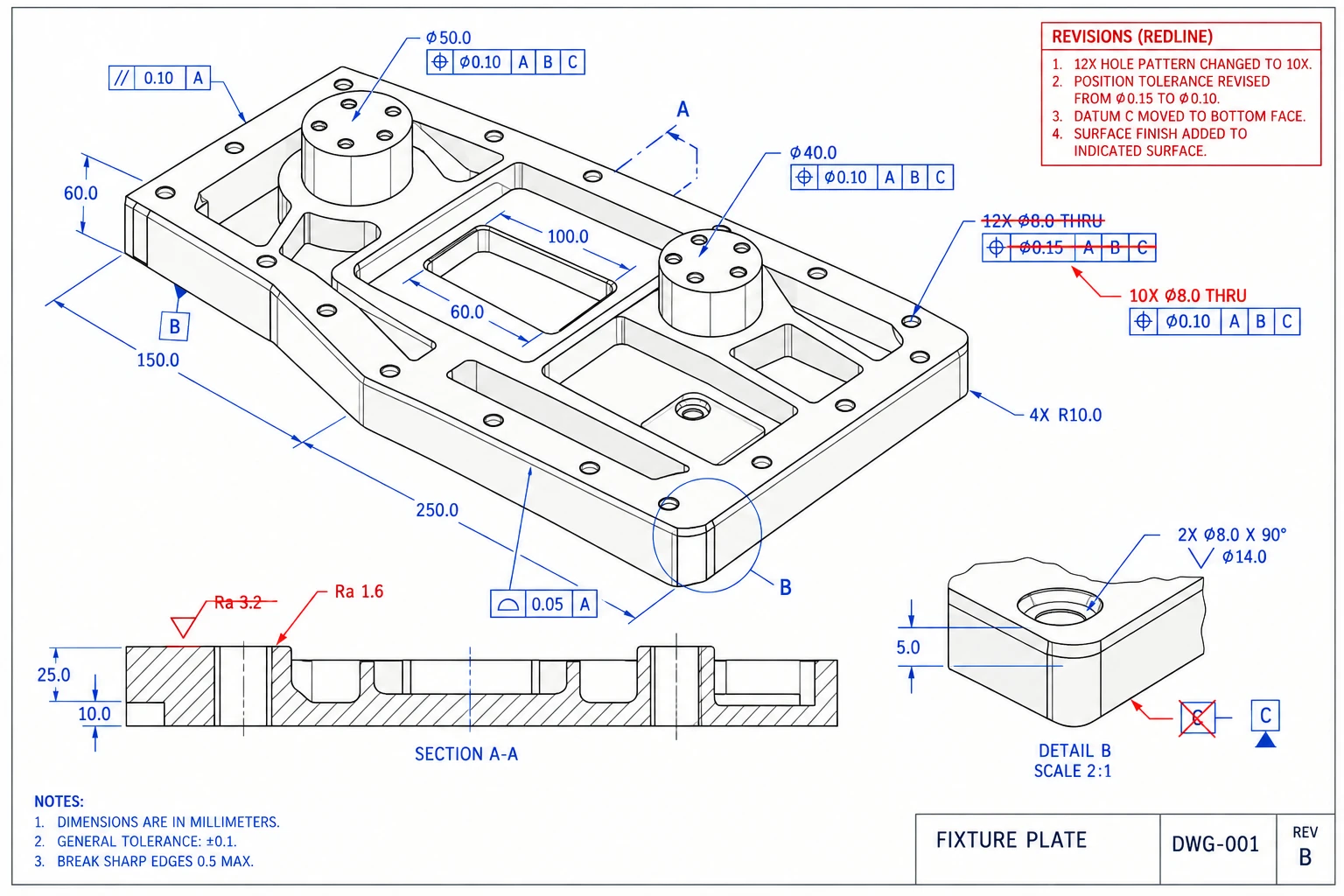
EXAMPLE 01
A hole-pattern change also changes inspection intent
In this fictional fixture-plate revision, a 12-hole mounting pattern becomes a 10-hole pattern, its positional tolerance is tightened, datum C moves to a different face, and a new surface-finish requirement is added. None of those edits should be reviewed alone: together they change how the part locates, how it is machined, and how a CMM inspection can establish the datum reference frame.
Before release, Manufacturing would need to confirm the setup and machining sequence. Quality would need to revise the CMM routine around the new datum reference frame and confirm that the new datum can be contacted repeatably. If the markup only circled the hole pattern, those connected changes could be missed.
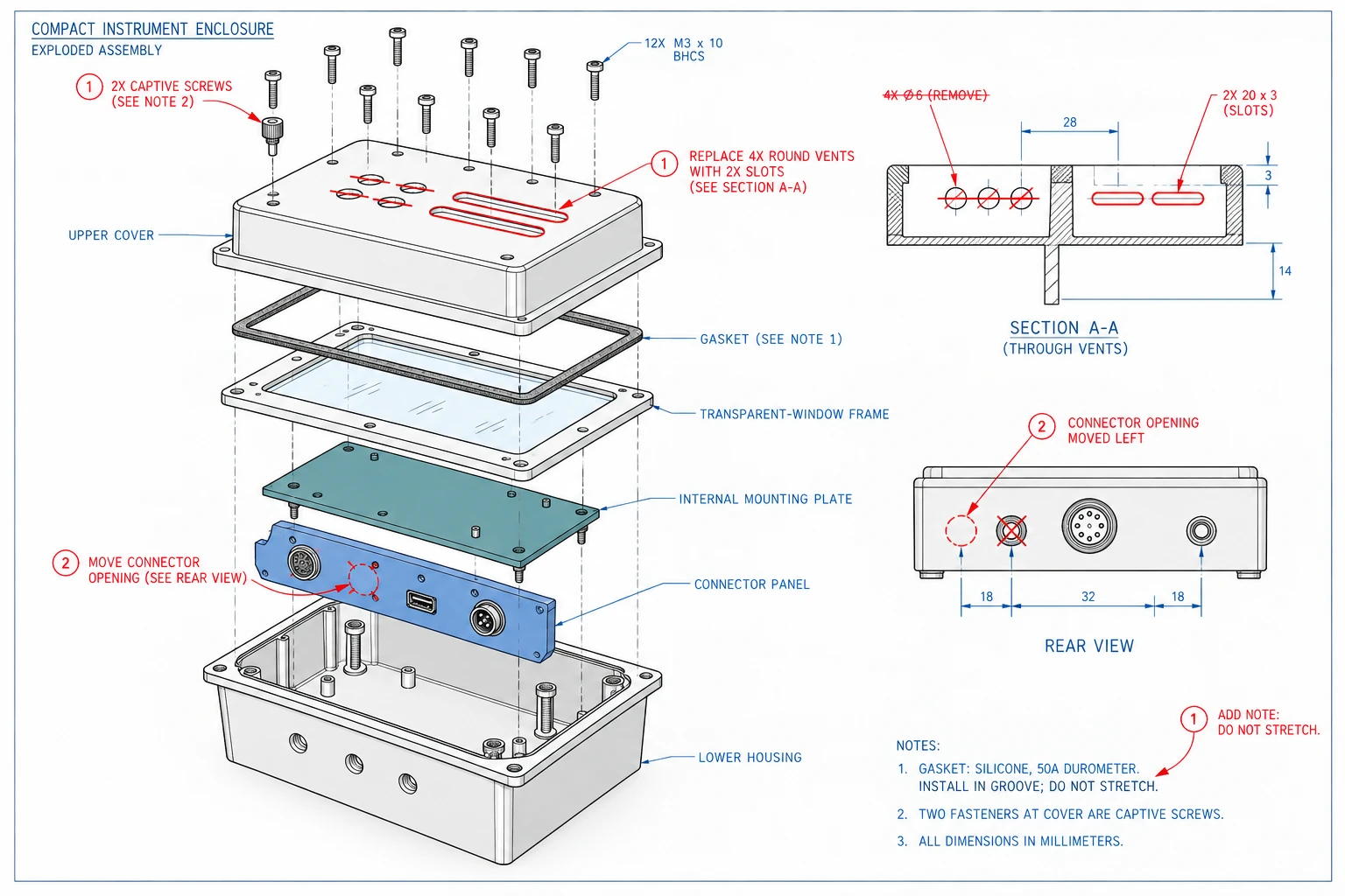
EXAMPLE 02
A revised cover can affect cooling, sealing, cabling, and service
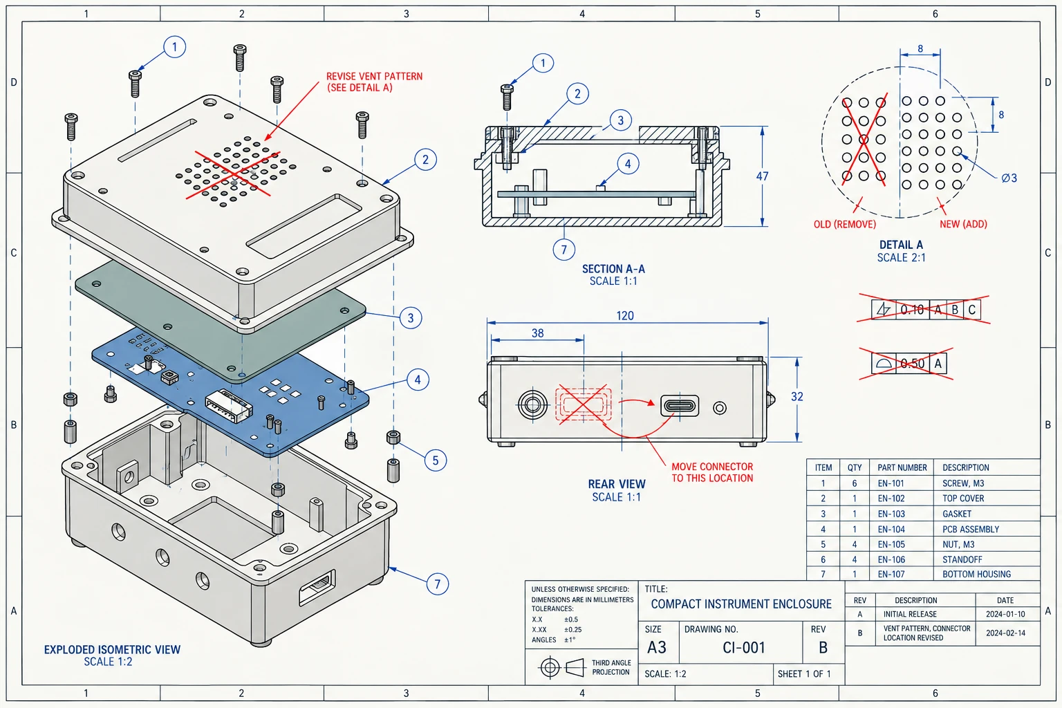
In this fictional enclosure revision, four circular vents become two slots, a connector opening moves, two cover fasteners become captive screws, and a gasket installation note is added. Each edit is easy to mark. The review is harder: the new vents may change airflow and ingress behavior, the connector may conflict with the internal plate or cable bend radius, and captive hardware changes the bill of materials and service procedure.
Thermal would review the change in open vent area. Mechanical would check internal clearance and cable bend radius. Quality would determine whether the gasket and connector position introduce new inspection characteristics. Service would review access to the captive fasteners. Each comment can point to the same proposed revision and the same baseline drawing.
Source basis: NIST’s public CAD and PMI test datasets, including the Box Assembly and Complex Test Models. NIST states that its engineering design repository and test artifacts are public domain. AutoRedline created these fictional derivatives for explanation; they do not represent NIST-approved revisions or customer work.
A public example of redlines in a controlled workflow
NASA Langley Research Center’s public procedure for hardware fabricated in its facilities includes a section specifically for drawing redline changes. The procedure describes returning a copy of the redlined drawing to engineering so the change can be incorporated into a revised drawing or a formal change request. It also separates authorization that allows manufacturing work to continue from the later controlled drawing revision.
The approval route and terminology vary between organizations, but the distinction is useful: the redline communicates what needs to change, while the revised drawing and formal change record make the approved result official. See section 2.2.2.4 of NASA Langley’s Fabrication of Research Hardware procedure.
How redlines help Development and Quality work together
Engineering may begin with design intent: is the proposed geometry correct and completely represented? Quality often begins with the requirement: what will be inspected, which earlier requirement is being replaced, and can the new requirement be verified consistently?
If the review package contains only the revised drawing, Quality must find the previous revision and recreate the comparison. If it contains only a numbered CAD marker, the reviewer may still need another document to understand the old and new values. A shared redline gives Engineering, Quality, Manufacturing, and the supplier the same before-and-after proposal to discuss.
Four questions before the ECO review starts
- What is the baseline? Identify the released revision or controlled working copy used for the comparison.
- What exactly is being replaced? Keep the previous value, note, or geometry identifiable.
- What is proposed? Show the new requirement at the affected location, not only in a separate paragraph.
- What else may be affected? Check repeated views, inspection plans, work instructions, tooling, risk controls, labeling, and service information as applicable.
Where the redline fits in an ECO workflow
- A change is proposed. The reason may come from development, testing, production, Quality, a supplier, or a customer requirement.
- The change is made visible. The redline connects the proposal to the affected drawing information.
- The impact is reviewed. The relevant functions check design intent, manufacturability, inspection, documentation, cost, and timing.
- The controlled revision is prepared and approved. The CAD drawing and associated records are updated through the organization’s formal process.
- The new revision is released. The approved drawing, not the redline, becomes the official definition.
What AutoRedline contributes
Preparing a redline manually can involve opening two PDFs, searching for changes, copying old values, drawing strikeouts and arrows, and then checking whether the markup is still legible. AutoRedline prepares a first pass from the original and revised PDFs so the reviewer can spend more time evaluating the changes and less time drawing every mark.
The generated marks are proposals. You can inspect the original, revised, and redline views at the same location; keep, edit, or remove proposed findings; add your own markup; and export the reviewed PDF for your engineering change package.
When evaluating the product, explore the prepared example, then use a revision pair your team has already reviewed and compare the output against your known change list. Check the exported PDF as well as the proposed marks.